In my previous post, I have shown the step-by-step guide to compile the basic hello-world demo of Contiki 2.7 for CC2538DK on Windows. Looking into the list of examples, the Contiki 2.7 is also delivered with a CC2538DK specific example which is located under contiki-2.7/examples/cc2538dk. The example shows basically basic input-output operation (push-button input, LED output), and also basic Rime broadcast communication (Rime is the light-weight wireless protocol used in Contiki).This blog post describes step-by-step guide to compile, run, and analyze the cc2538dk example of Contiki 2.7.
Compiling CC2538DK Example
Compiling the cc2538dk example is really similar to the hello-world example which is described in my previous post. Use the Cygwin terminal to navigate to the example folder (e.g. in my case since I extracted the Contiki 2.7 package under C:/work, the cygwin folder is /cygwin/c/work/contiki-2.7/examples/cc2538dk). Execute “make TARGET=cc2538dk” at the folder and wait until the cc2538-demo.bin is successfully generated.
Anyway, I must admit that I am somehow spoiled with the usage of IDE. Working with only text editors (I normally user Notepad++) and Contiki package is somehow difficult for me. I found a way to compile the example project using the Code::Blocks IDE. The Code::Blocks project file (.cbp) can be downloaded from my google drive.
Download the ZIP file and extract it to find the cc2538-demo.cbp project file. Put it under the contiki-2.7/examples/cc2538dk. Open it using the Code::Blocks IDE (I am using Code::Blocks v13.12 for Windows), and first make sure that the compiler setting is correct by going to “Settings” -> “Compiler…”. do “Build”.
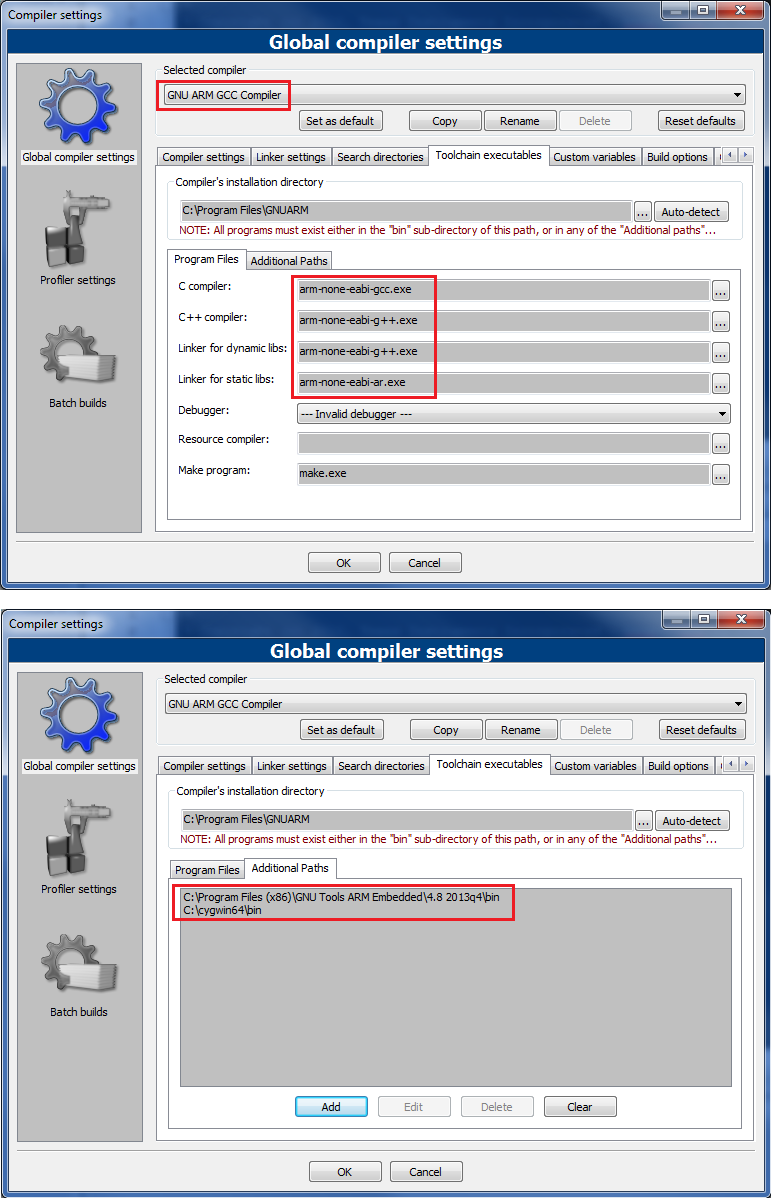
In the compiler setting window, choose the “GNU ARM GCC Compiler” as the selected compiler, make sure that the compiler binaries prefix is “arm-none-eabi-“, and finally add the path to the GNU ARM compiler toolchain binaries and also cygwin (for the make.exe) folder under the “Additional Paths” tab:
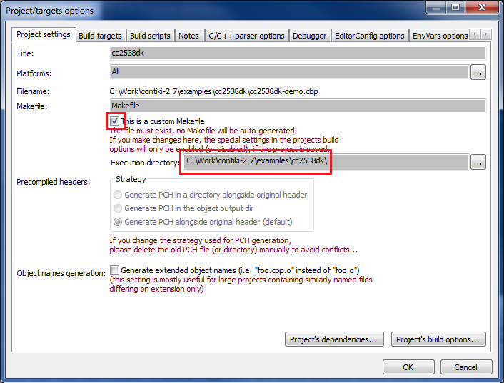
Under “Project” -> “Properties” -> “Project settings” tab, make sure that the option “This is a custom Makefile” is checked and the execution directory points to the contiki-2.7/examples/cc2538dk folder.
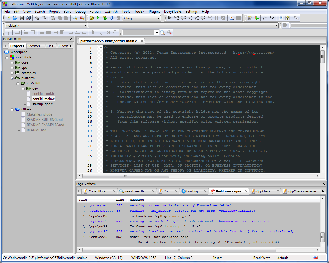
After that, it should be safe to execute “Build” and wait until the cc2538-demo.bin is generated after successful compilation. The following screenshot shows how the cc2538dk example is successfully built:
Notice that it is not possible to compile single file using the Code::Blocks IDE with the settings described above. However it is much easier now (at least for me) to navigate between files, doing search, and also finding declarations/implementations of functions, variables, macros, etc.
Running the CC2538DK Demo
After successfully building the cc2538-demo.bin binary, flash it to the hardware kit using SmartRF Flash Programmer v2. Open a hyper-terminal like software on the PC, and set the UART setting to 115200 8N1 to see the following output:

As described in the cc2538-demo.c source file, the users can interact with the demo using the on-board CC2538DK push-buttons by the following manner:
- Down and Up Buttons: rebooting system (using watchdog and soft reset respectively)
- Left and Right Buttons: Blinking LED1
- Select Button: transmit a Rime broadcast message.
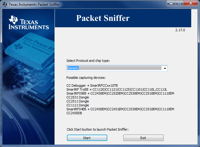
In order to sniff the Rime broadcast message, I am using the CC2531 USB dongle which is delivered within the CC2538DK. Using the SmartRF Flash Programmer v1, flash the sniffer firmware to CC2531 USB dongle (filename: sniffer_fw_cc2531.hex, usually located under /SmartRF Tools/Packet Sniffer/bin/general/firmware) – CC-Debugger is needed as hardware programmer interface. Download and install the SmartRF Packet Sniffer from TI website. Start SmartRF Packet Sniffer, and choose “Generic” protocol:
Then, select the “CC2531 USB Dongle”as capturing device and set the IEEE 802.15.4 Channel option as 0x19 under “Radio Configuration” tab. This corresponds to the default channel setting declaration CC2538_RF_CONF_CHANNEL definition in platform/cc2538dk/contiki-conf.h. Start the packet sniffer and press the select button on the CC2538DK to see the transmitted Rime broadcast messages as follows:
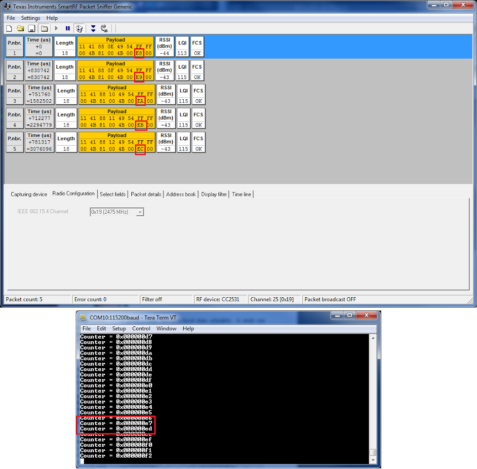
As seen above, if the select button is pressed, the counter variable will be sent as transmitted Rime broadcast data instead printed out via UART (detail information can be read directly from the source code contiki-2.7/examples/cc2538dk/cc2538-demo.c).
Testing The Rime Broadcast Communication with Multiple CC2538DK Boards
As the CC2538DK is delivered with a pair of SmartRF06EB-CC2538EMK, I am trying to check the Rime broadcast communication between the two boards. The cc2538-demo description says that besides transmitting a Rime broadcast message, the node shall printout the received messages via UART.
First of all, I found out that the local address node of the Rime stack for the CC2538DK demo is initialized with the last two bytes of the hardware 64 bit IEEE address of the CC2538 device which should be unique. However it seems that both of the CC2538s on my kit has the same IEEE address of 02:F4:AE:07:0:12:4B:00 (4B:00 is then used for the Rime stack address). Therefore it is necessary to bypass this address assignment process which can be done by modifying the contiki-conf.h configuration header file.
Open the contiki-conf.h header file which can be found under contiki-2.7/platform/cc2538dk/ folder. Set the IEEE_ADDR_CONF_HARDCODED as 1 and set the IEEE_ADDR_CONF_ADDRESS as wished but must be different for each board. Re-compile the demo for each board with different IEEE_ADDR_CONF_ADDRESS setting.
/*---------------------------------------------------------------------------*/
/**
 * \name IEEE address configuration
 *
 * Used to generate our RIME & IPv6 address
 * @{
 */
/**
 * \brief Location of the IEEE address
 * 0 => Read from InfoPage,
 * 1 => Use a hardcoded address, configured by IEEE_ADDR_CONF_ADDRESS
 */
#ifndef IEEE_ADDR_CONF_HARDCODED
#define IEEE_ADDR_CONF_HARDCODED             1
#endif

/**
 * \brief The hardcoded IEEE address to be used when IEEE_ADDR_CONF_HARDCODED
 * is defined as 1
 */
#ifndef IEEE_ADDR_CONF_ADDRESS
#define IEEE_ADDR_CONF_ADDRESS { 0x00, 0x12, 0x4B, 0x00, 0x89, 0xAB, 0xCD, 0xEE }
#endif
/** @} */
/*---------------------------------------------------------------------------*/
I used one with 0xCD, 0xEF ending and 0xCD, 0xEE ending for the other. According to the description in the README.md file, it is also possible to override the IEEE address when IEEE_ADDR_CONF_HARDCODED is set as 0 with the NODE_ID make command parameter, for example:
$ make NODEID=0xCDEE
After flashing the generated binaries to each board, I can see that the Rime broadcast message can be transmitted from one board and received by the other board.
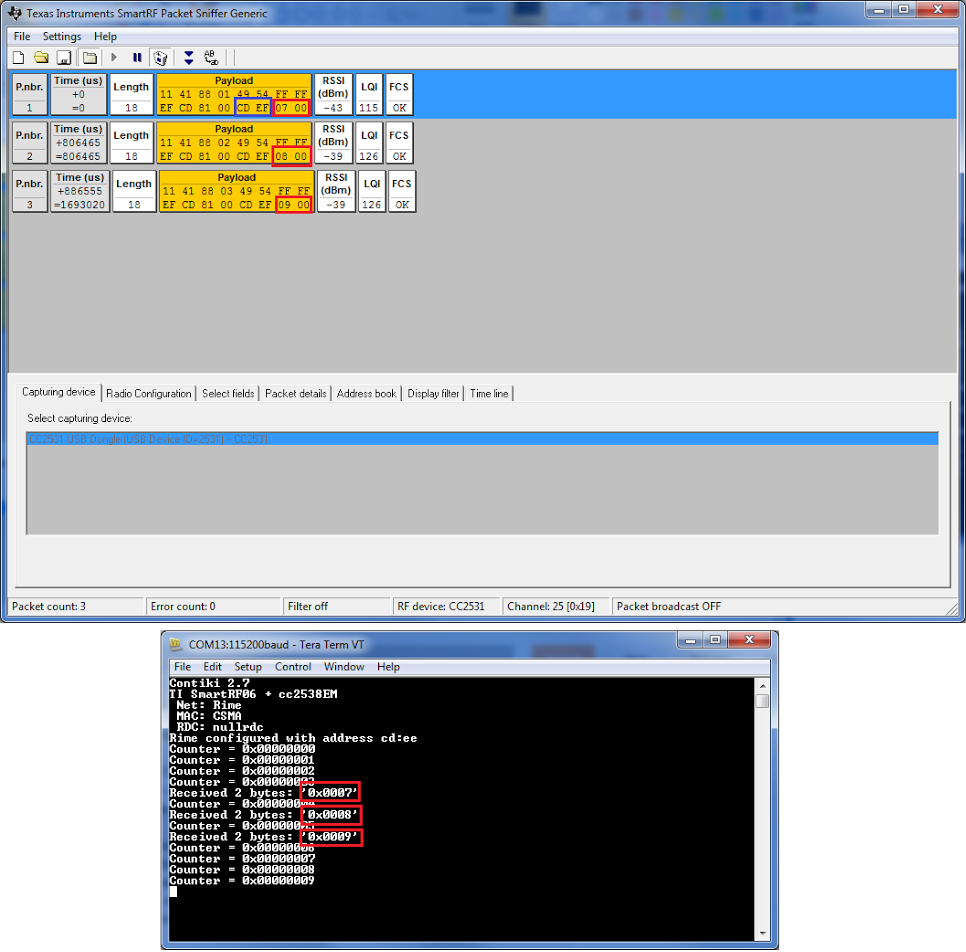
The screenshot above shows that the sniffer dumps messages sent by the board with 0xCD, 0xEF address and received by the board with 0xCD, 0xEE address (in the sniffer window, the last four bytes in each packet contains sender address and data respectively).
I am still struggling to find out detail information the Rime protocol (e.g. packet format, topology), and it seems I need to look into the source code to find it out (haven’t found anything useful by googling until now). The best sources I found so far is either this presentation or this discussion. I will come back with some more information later if I get more findings.
Thanks very much!
One of the best hands-on on installing and compiling Contiki under Windows!
Contiki promises to be one of the best LPW OS, but it’s very difficult to surf the code and the documentation available on web is not so good and very confusing.
I’ll continue to follow your very clear “lessons”!
Giovanni
Thanks, Giovanni. I wish I had more time to work on this. Anyway, I am preparing a guide to debug CC2538DK, but need more time to finish it. Stay tuned 😉
Nice work. Can you please give information about contiki 2.7 and cc2530. need to get hex file from contiki to dump on cc2530.
Thanks Leo,
The above example worked fine for me in Contiki. I am able to see the output in LINUX terminal window within Instant-Contiki-2.7.
However, on using Coolterm (host machine i.e. on Windows 7), I am able to see only transmitter output but not Receiver output owing to 104 Framing Error, 103 break error, etc.
How do I debug it to see the receiver output?
Thanks a lot,
Indrajit
Hi thanks for the lovely information it was indeed very useful. I am trying to get a working code that will upload sensor data onto cloud like thingspeak using http. Are you aware about any such working code.
Hi Leo,
Did you install the Code::Blocks with the TDM-GCC compiler? They have 3 available downloadable options.
Thanks for your guide.
Cheers,
TG
Hi
Thanks.Everything worked perfectly!
You have made a file xx.cbp so that I could build example cc2538dk. Does same cbp works for all examples else how it can be created?
Regards
Hanish